Temperature Sensors Part 4: PCBs and Programming
This is post number 4 in a series describing my DIY temperature and humidity sensors.
Printed Circuit Boards
For the past month my two prototype sensors have been dutifully reporting the temperature and humidity in my house with any complaint. At this point I want to get a PCB made to make assembly easier. I’ve never done any serious board layout, but learn.sparkfun.com has an well-written, two-part tutorial called Using EAGLE.
This is what I came up with after an evening of work:
I decided to order the boards from OSH Park who are charging me a grand total of $7.35 for three boards (with free shipping!).
These differ from my hand-made prototypes in two ways:
- I’ve added a three holes on the board (labeled J3) for easy access to VCC, 3.3V, and GND
- There’s a button! More on that in the next section
Programming Changes
Up to this point all of the sensor’s settings have been hard-coded in the program. If I wanted to change a sensor’s name, it’s recording interval, or the InfluxDB server it reported to I had to change the program and re-flash the ESP8266 with the new version.
This process entails the following:
- Remove ESP8266 from sensor and place on breadboard
- Attach FTDI breakout to the breadboard
- Connect FTDI and ESP8266 together going through a level shifter
- Make changes to program
- Flash the new program to ESP8266
- Put ESP8266 back in sensor
I made a jig to make this process easier, but it’s a pain, and if you need an FTDI breakout to program this sensor it drives the cost up even more at $15.95 for the FTDI breakout (you could also use an Arduino UNO with the ATMEGA removed, but that’s even more of a pain) and $2.95 for a logic level converter .
This is where the button comes in. If you hold the button down while plugging the sensor in it will enter configuration mode. In this mode the sensor acts as a Wi-Fi hotspot and broadcasts a network called “Sensor Setup”. Navigating to 192.168.4.1 provides configuration options.
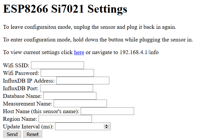
These settings are saved in the ESP8266’s flash memory so they persist across power cycles. To leave the configuration mode, simply unplug the sensor and plug it back in again.
“But wait!” you cry, “doesn’t the ESP8266 only have two GPIO pins in this configuration? And you’re using them both for I2C to communicate with the sensor!” And in fact you’re right, only two pins are dedicated to GPIO in this configuration… but the RX and TX pins can be repurposed as GPIO pins. Check out how on Stack Overflow.
The full code can be found on Github