Daniel's Weblog
Posts About
Tags Colophon

Tags / ESP8266 Temp Sensor

Temperature Sensors Part 5: Assembling PCBs & Future Plans

I finally received my printed circuit boards in the mail, time to assemble them.

This is post number 5 in a series describing my DIY temperature and humidity sensors.

Printed Circuit Boards

OSH Park’s packaging is not subtle.

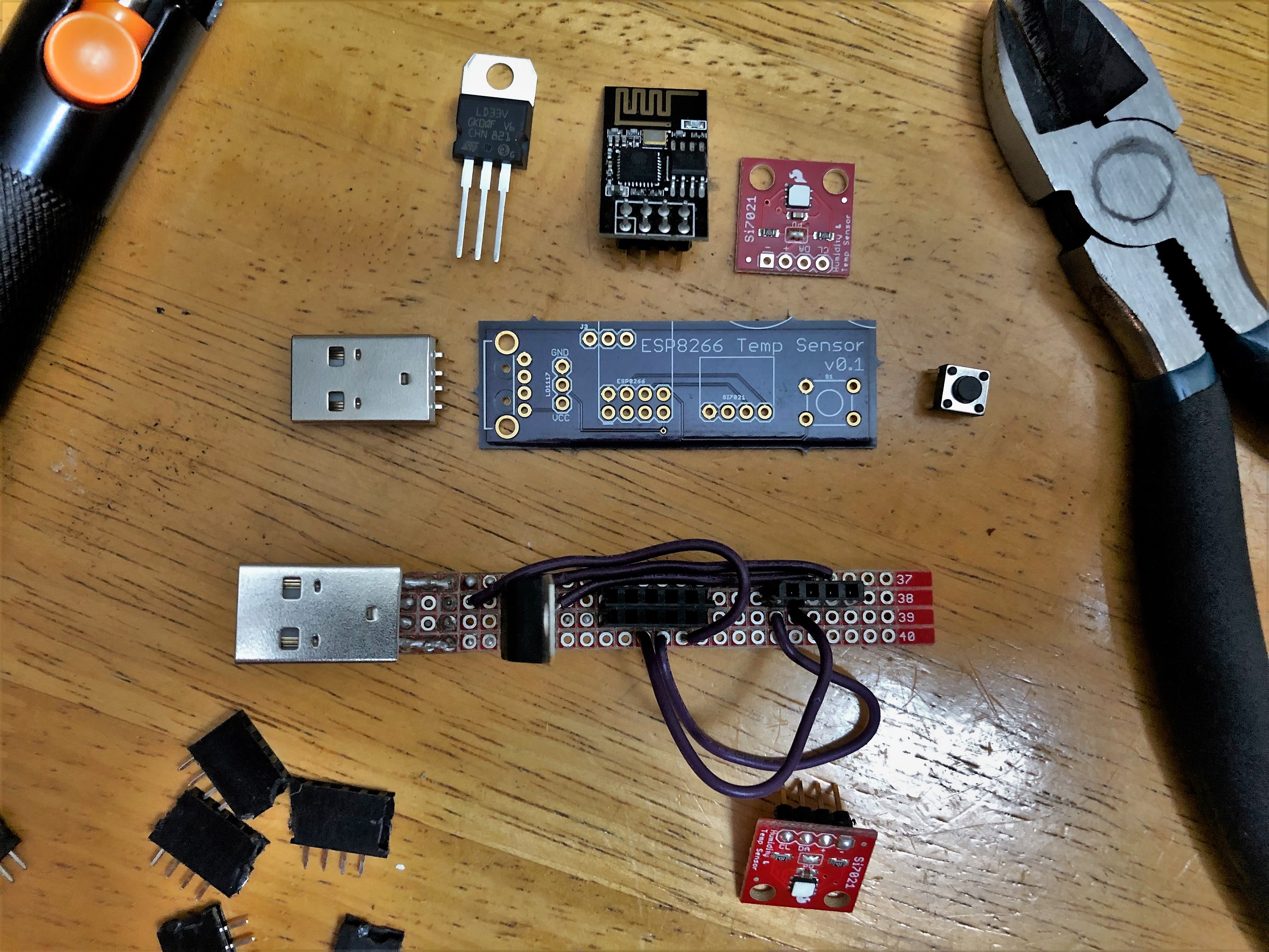
The boards are indeed a dark purple, which my camera didn’t properly capture. Here’s what they look like unpopulated and populated:

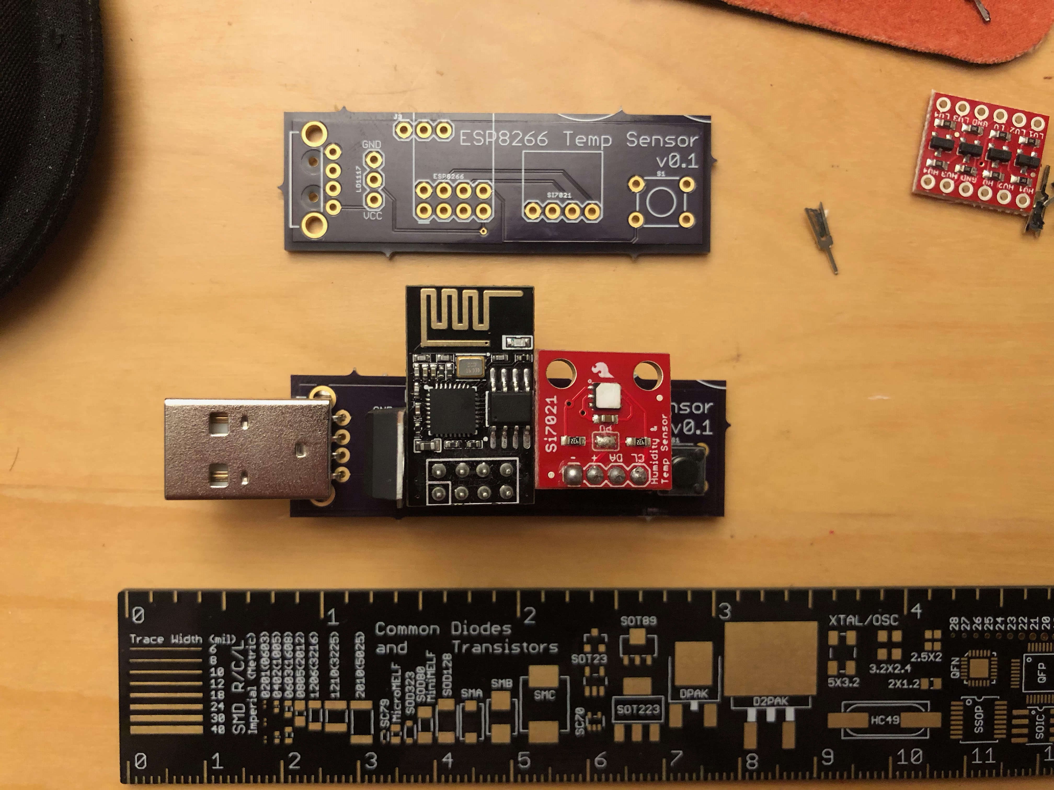
On the top right there’s a little bit of what I can only assume is someone else’s screen printing that overlapped on to my board. No harm done, and it adds character. The little points that held the panel together during production are rather sharp, I ended up cutting off the points so I wouldn’t stab myself.

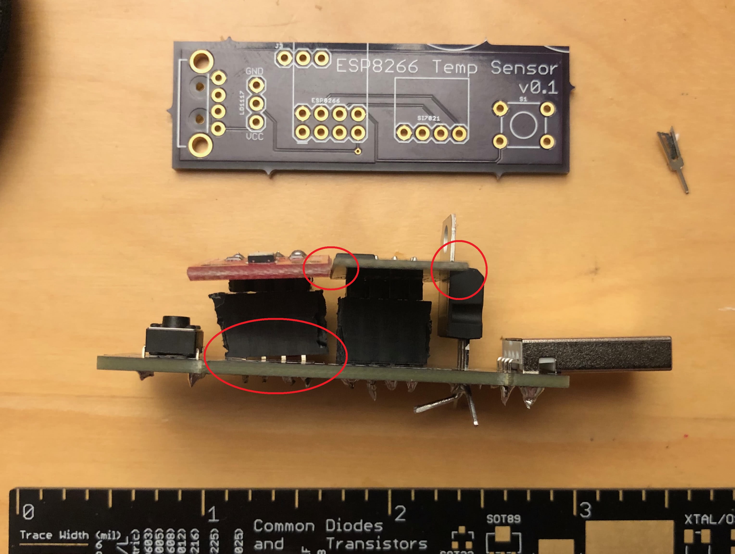
It’s not perfect, though. The empty space between components is smaller than it seemed on the computer screen and I didn’t leave enough space between the components. I had to tilt headers connecting to the temperature sensor so it would fit along side the ESP8266.

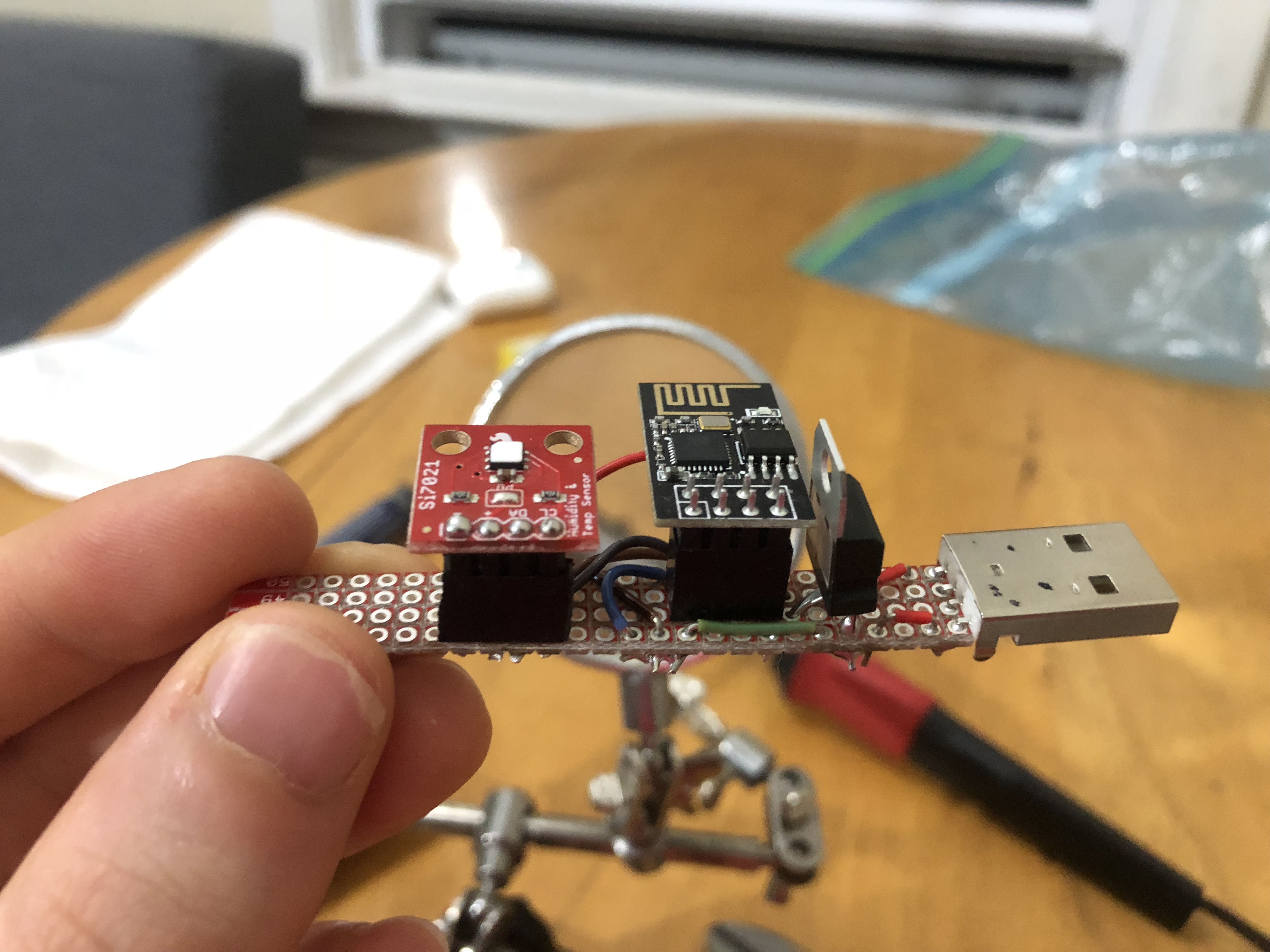
Despite that, it’s definitely an improvement over the hand-made version.

Future Plans

So where to go from here? I’ve been using this for temperature sensors, but in reality I’ve created a 3.3V based I²C base for the ESP8266. I could replace the temperature sensor with…

  • Another atmospheric monitoring sensor with barometric pressure as well
  • An infrared array to determine if a human (or dog, maybe?) is present
  • A 16x2 LCD Display that could easily update over Wi-Fi
  • A Sparkfun Qwicc Adapter so I can daisy-chain many I²C sensors together (An external power supply may be required, depending on how crazy you want to get)

But it doesn’t have to be limitted to I²C interfaces!

  • I’ve been thinking about using a non-invasive current sensor so I don’t have to walk all the way to the basement to check on the washer and dryer
  • A particulate matter sensor so I can detect air polution hazards (like if my housemate is cooking extremely spicy chicken)
  • Or even something as simple as a reed switch to tell if a door is open

Temperature Sensors Part 4: PCBs and Programming

This is post number 4 in a series describing my DIY temperature and humidity sensors.

Printed Circuit Boards

For the past month my two prototype sensors have been dutifully reporting the temperature and humidity in my house with any complaint. At this point I want to get a PCB made to make assembly easier. I’ve never done any serious board layout, but learn.sparkfun.com has an well-written, two-part tutorial called Using EAGLE.

This is what I came up with after an evening of work:

I decided to order the boards from OSH Park who are charging me a grand total of $7.35 for three boards (with free shipping!).

These differ from my hand-made prototypes in two ways:

  1. I’ve added a three holes on the board (labeled J3) for easy access to VCC, 3.3V, and GND
  2. There’s a button! More on that in the next section

Programming Changes

Up to this point all of the sensor’s settings have been hard-coded in the program. If I wanted to change a sensor’s name, it’s recording interval, or the InfluxDB server it reported to I had to change the program and re-flash the ESP8266 with the new version.

This process entails the following:

  1. Remove ESP8266 from sensor and place on breadboard
  2. Attach FTDI breakout to the breadboard
  3. Connect FTDI and ESP8266 together going through a level shifter
  4. Make changes to program
  5. Flash the new program to ESP8266
  6. Put ESP8266 back in sensor

I made a jig to make this process easier, but it’s a pain, and if you need an FTDI breakout to program this sensor it drives the cost up even more at $15.95 for the FTDI breakout (you could also use an Arduino UNO with the ATMEGA removed, but that’s even more of a pain) and $2.95 for a logic level converter .

This is where the button comes in. If you hold the button down while plugging the sensor in it will enter configuration mode. In this mode the sensor acts as a Wi-Fi hotspot and broadcasts a network called “Sensor Setup”. Navigating to 192.168.4.1 provides configuration options.

These settings are saved in the ESP8266’s flash memory so they persist across power cycles. To leave the configuration mode, simply unplug the sensor and plug it back in again.

“But wait!” you cry, “doesn’t the ESP8266 only have two GPIO pins in this configuration? And you’re using them both for I2C to communicate with the sensor!” And in fact you’re right, only two pins are dedicated to GPIO in this configuration… but the RX and TX pins can be repurposed as GPIO pins. Check out how on Stack Overflow.

The full code can be found on Github


Temperature Sensors Part 3: Sensor Hardware

This is post number 3 in a series describing my DIY temperature and humidity sensors.

The Sensor:

Profile view of the sensor

Hardware Breakdown:

The sensors themselves are pretty simple, consisting of only five components.

Not including solder, various lengths of wire, and the perf board that the components are mounted on. I used a Sparkfun Snappable Protoboard ($7.95) as the base for each of my sensors.

  1. ESP8266 WiFi Module ($6.95)
  2. Si7021 Humidity and Temperature Breakout Board ($7.95)
  3. LD1117V33 Voltage Regulator ($1.95)
  4. USB Type A plug ($1.50)

Total cost before tax: $18.35

Prices given are from Sparkfun as of September, 2018

Design Choices:

The goal was a sub-twenty dollar, reasonably accurate temperature sensor that I could place anywhere in my house and forget about.

Data Transmission

I want to store this data in InfluxDB (Detailed in Part I) so I can visualize it in Grafana (Detailed in Part II).

My house isn’t wired for Ethernet– if it was I could solve both the transmission and power problems with Power over Ethernet.

In the past I’ve worked with the Nordic NRF24L01+ radios which are reasonabley priced and have decent range, but I would need some sort of relay that could receive the wireless transmission and send it over TCP/IP to the InfluxDB. Someone has done this, but it seems like extra work when I already have a Wi-Fi network in my house.

So I went with the ESP-8266 Wi-Fi module because I had two laying around. Future iterations may use a different version of the chip.

Power

Some impressive work has been done making the ESP8266 run on batteries for a very long time, but batteries eveuntally need charging or changing.

What I do have lying around though, is a bunch of USB wall chargers that can put out 5V and more than enough amperage which, using a LD1117, can be converted from 5V into the 3.3V that the ESP-8266 and sensor need. The ESP-8266 only consumes 170mA tops and the Si7021 sensor uses all of 150 μA, so the LD1117’s max of 800mA is overkill, but hey, I majored in Computer Science and it seems like a good solution to me.

In summary 120V AC power comes out of the wall, gets converted to 5V DC by the USB wall charger, which the sensor is plugged in to. Onboard the circuit board the voltage is dropped again to 3.3V which the radio and the sensor can use.

Right now I’m only using the USB power and ground lines, but I dream of being able to fit some sort of USB Serial Adapter and a logic level converter so that the ESP-8266 can be programmed directly from the USB port. At the moment it’s a bit of a pain to change Wi-Fi networks, I have to remove the ESP8266, and plug it into a jig to reprogram it.

In Action

Sensor plugged into wall outlet

One issue is that a lot of stress can be put on the pins connecting the USB port to the sensor board.

USB connector broken off of circuit board


Temperature Sensors Part 2: Grafana

Recording temperature into InfluxDB isn’t very useful if I can’t visualize it. Thanksfully, Grafana exists.

This is part 2 in a series describing my DIY temperature and humidity sensors.

Grafana Setup

I have Grafana running on the same webserver as this website, configured with two different data sources:

  1. My InfluxDB server (Currently a Raspberry Pi)
  2. The DarkySky.net plugin for an approximate idea of the outside temperature (Plotted as apparentTemperature on the graph below)

Records:

  • The recorded temperature in my room was 56.09°F on October 19th at 8 AM. Later that day the heat was turned on
  • Since the heat has been turned on:
    • Living room:
      • Max Low: 67°F
      • Max High: 68.34°F
    • My Room:
      • Max Low: 36.65°F
      • Max High: 75.02°F

Takeaways

  • My third floor room is colder than the second floor living room directly below by about 5-7°F on average.
  • Turning on the living room ceiling fan lowers the living room temperature, but does not change the temperature in my room.

Actual Graphs

Below is a “snapshot” of the data my temperature sensors collected between Oct 22nd and Oct 29th, 2018. To make it load quickly I’ve set the resolution to 30 minutes (each point on this plot is the average of the past 30 minutes).

Temperature Graph (Direct)

I’m also collecting relative humidity data:

Relative Humidity Graph (Direct)


Temperature Sensors Part 1: Influx DB

This is part 1 in a series describing my DIY temperature and humidity sensors.

I built some temperature and humidity sensors based on ESP8266 Wi-Fi modules for house so I know just how cold I am at any given moment. This details the settings on the InfluxDB server that stores everything. I made package this up in to a little library (Github) to make things easier.

InfluxDB

Each sensor has it’s own measurement (the name of the room they’re located in) and updates the database multiple times per minute. This is excessive, but I forgot about it and it’s a bit of pain to reprogram them.

name: DanielsRoom
time                           fahrenheit host                 region  relative_humidity
----                           ---------- ----                 ------  -----------------
2018-10-20T00:00:02.328505836Z            esp8266-DanielsRoom1 us-east 0.547224
2018-10-20T00:00:03.528801987Z 72.574486  esp8266-DanielsRoom1 us-east 
2018-10-20T00:00:03.768001235Z            esp8266-DanielsRoom1 us-east 0.547147
2018-10-20T00:00:04.687234974Z 72.574486  esp8266-DanielsRoom1 us-east 
name: LivingRoom
time                           fahrenheit host                region  relative_humidity
----                           ---------- ----                ------  -----------------
2018-10-20T00:00:02.643783571Z 72.207687  esp8266-LivingRoom1 us-east 
2018-10-20T00:00:03.048582528Z            esp8266-LivingRoom1 us-east 0.504728
2018-10-20T00:00:03.79192576Z  72.188385  esp8266-LivingRoom1 us-east 
2018-10-20T00:00:04.052576581Z            esp8266-LivingRoom1 us-east 0.504651

LivingRoom and DanielsRoom belong to a retention policy called two_hours which stores the data points for… two hours!

name      duration shardGroupDuration replicaN default
----      -------- ------------------ -------- -------
autogen   0s       168h0m0s           1        false
two_hours 2h0m0s   1h0m0s             1        true
forever   0s       168h0m0s           1        false

Long before the two hour time limit is up a continuous query runs and calculates the average sensor value for the past minute and stores it in the forever retention policy which keeps it forever.

name: 
name                               query
----                               -----
cq_1m_danielsroom_humidity         CREATE CONTINUOUS QUERY cq_1m_danielsroom_humidity ON  BEGIN SELECT mean(relative_humidity) AS mean_relative_humidity INTO HouseholdDatabase.forever.danielsroom_relative_humidity FROM HouseholdDatabase.two_hours.DanielsRoom GROUP BY time(1m) END
cq_1m_danielsroom_fahrenheit       CREATE CONTINUOUS QUERY cq_1m_danielsroom_fahrenheit ON  BEGIN SELECT mean(fahrenheit) AS mean_fahrenheit INTO HouseholdDatabase.forever.danielsroom_fahrenheit FROM HouseholdDatabase.two_hours.DanielsRoom GROUP BY time(1m) END
cq_1m_livingroom_fahrenheit        CREATE CONTINUOUS QUERY cq_1m_livingroom_fahrenheit ON  BEGIN SELECT mean(fahrenheit) AS mean_fahrenheit INTO HouseholdDatabase.forever.livingroom_fahrenheit FROM HouseholdDatabase.two_hours.LivingRoom GROUP BY time(1m) END
cq_1m_livingroom_relative_humidity CREATE CONTINUOUS QUERY cq_1m_livingroom_relative_humidity ON  BEGIN SELECT mean(relative_humidity) AS mean_relative_humidity INTO HouseholdDatabase.forever.livingroom_relative_humidity FROM HouseholdDatabase.two_hours.LivingRoom GROUP BY time(1m) END