I finally received my printed circuit boards in the mail, time to assemble them.
Other Posts in this Series:
This is post number 5 in a series describing my DIY temperature and humidity sensors.
Part I: InfluxDB Settings
Part II: Grafana
Part III: The Hardware
Part IV: PCBs and Programming
Printed Circuit Boards
OSH Park’s packaging is not subtle.

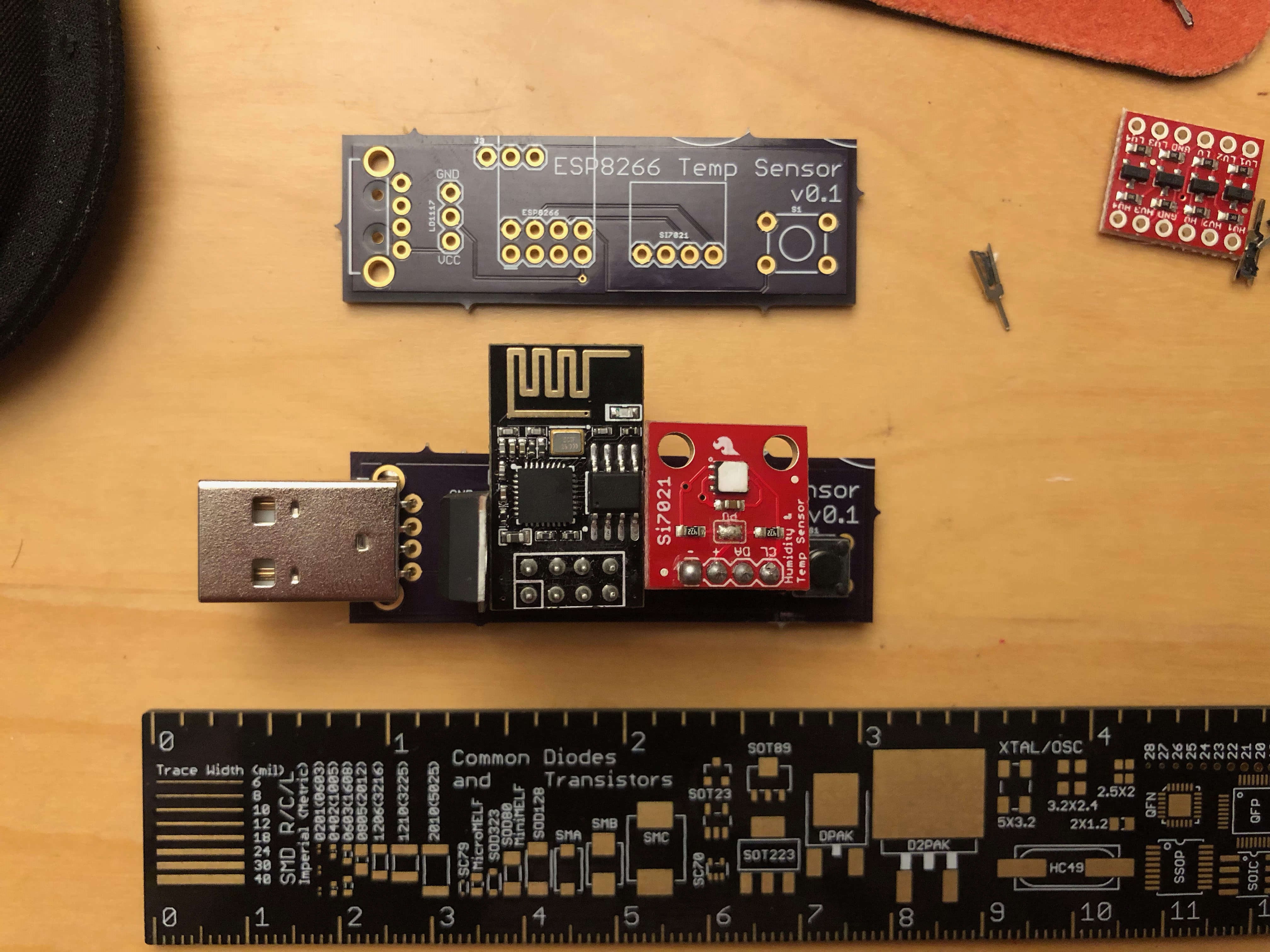
The boards are indeed a dark purple, which my camera didn’t properly capture. Here’s what they look like unpopulated and populated:

On the top right there’s a little bit of what I can only assume is someone else’s screen printing that overlapped on to my board. No harm done, and it adds character. The little points that held the panel together during production are rather sharp, I ended up cutting off the points so I wouldn’t stab myself.
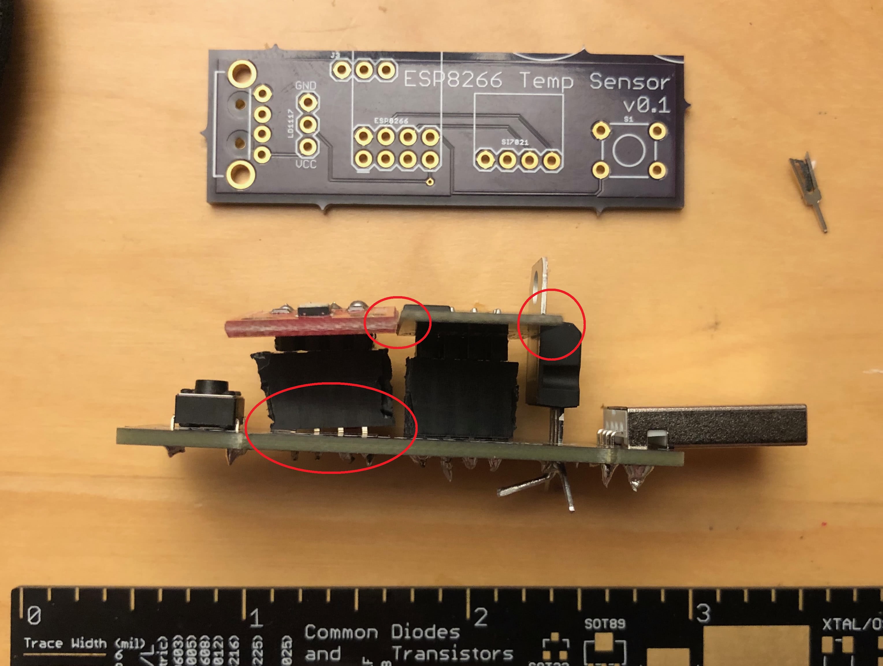
It’s not perfect, though. The empty space between components is smaller than it seemed on the computer screen and I didn’t leave enough space between the components. I had to tilt headers connecting to the temperature sensor so it would fit along side the ESP8266.

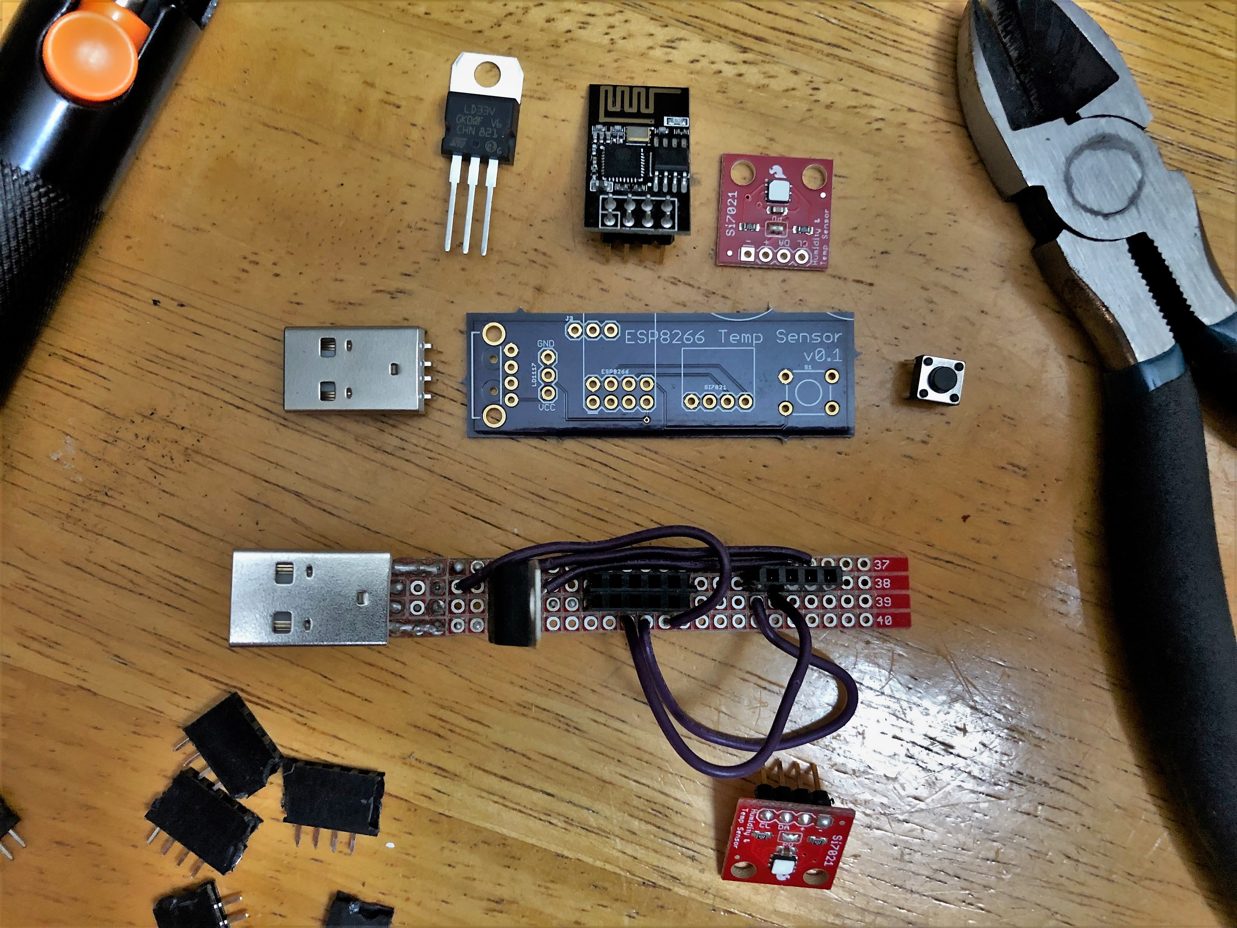
Despite that, it’s definitely an improvement over the hand-made version.

Future Plans
So where to go from here? I’ve been using this for temperature sensors, but in reality I’ve created a 3.3V based I²C base for the ESP8266. I could replace the temperature sensor with…
- Another atmospheric monitoring sensor with barometric pressure as well
- An infrared array to determine if a human (or dog, maybe?) is present
- A 16x2 LCD Display that could easily update over Wi-Fi
- A Sparkfun Qwicc Adapter so I can daisy-chain many I²C sensors together (An external power supply may be required, depending on how crazy you want to get)
But it doesn’t have to be limitted to I²C interfaces!
- I’ve been thinking about using a non-invasive current sensor so I don’t have to walk all the way to the basement to check on the washer and dryer
- A particulate matter sensor so I can detect air polution hazards (like if my housemate is cooking extremely spicy chicken)
- Or even something as simple as a reed switch to tell if a door is open