Temperature Sensors Part 3: Sensor Hardware
This is post number 3 in a series describing my DIY temperature and humidity sensors.
The Sensor:
Hardware Breakdown:
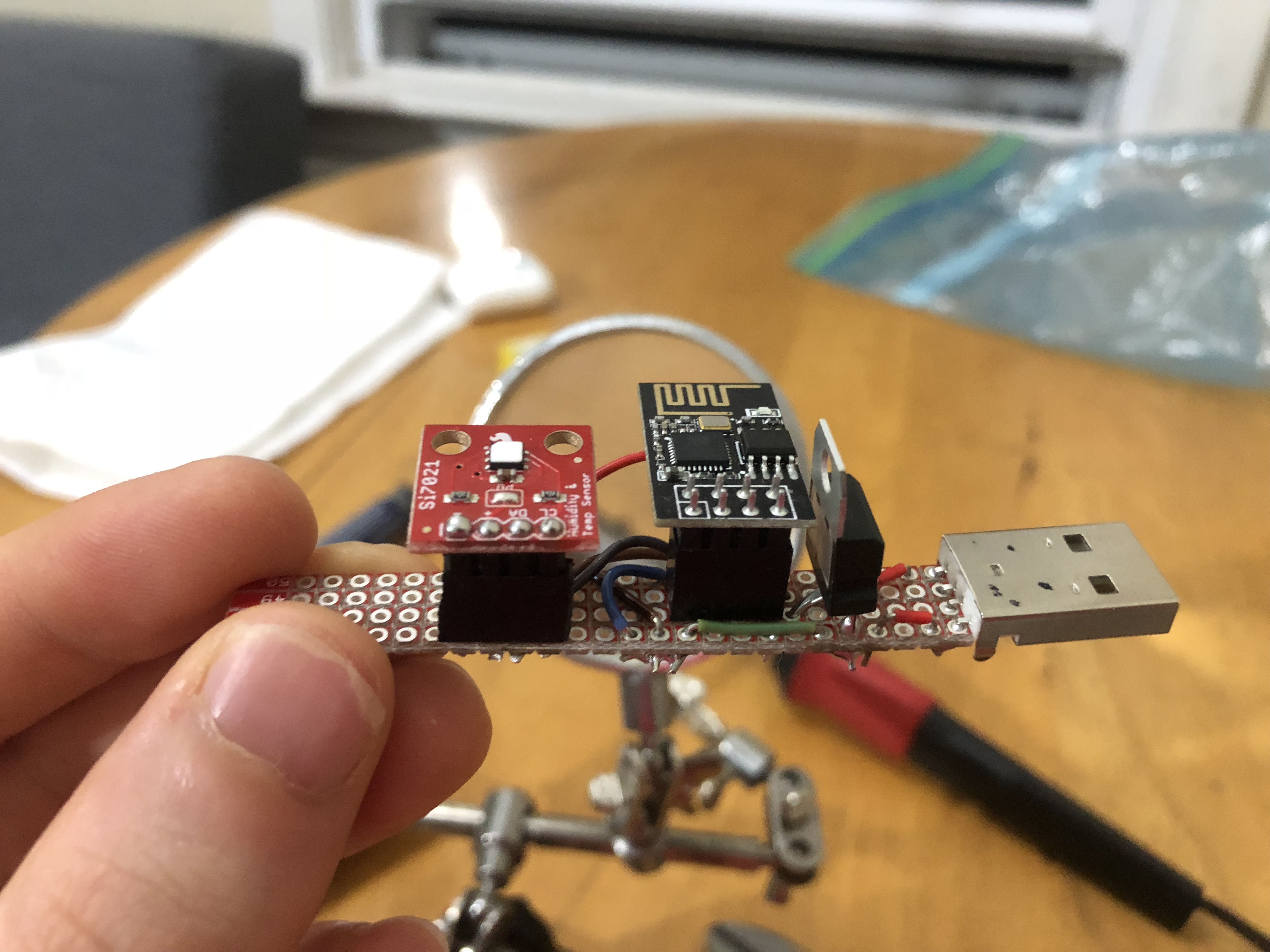
The sensors themselves are pretty simple, consisting of only five components.
Not including solder, various lengths of wire, and the perf board that the components are mounted on. I used a Sparkfun Snappable Protoboard ($7.95) as the base for each of my sensors.
- ESP8266 WiFi Module ($6.95)
- Si7021 Humidity and Temperature Breakout Board ($7.95)
- LD1117V33 Voltage Regulator ($1.95)
- USB Type A plug ($1.50)
Total cost before tax: $18.35
Prices given are from Sparkfun as of September, 2018
Design Choices:
The goal was a sub-twenty dollar, reasonably accurate temperature sensor that I could place anywhere in my house and forget about.
Data Transmission
I want to store this data in InfluxDB (Detailed in Part I) so I can visualize it in Grafana (Detailed in Part II).
My house isn’t wired for Ethernet– if it was I could solve both the transmission and power problems with Power over Ethernet.
In the past I’ve worked with the Nordic NRF24L01+ radios which are reasonabley priced and have decent range, but I would need some sort of relay that could receive the wireless transmission and send it over TCP/IP to the InfluxDB. Someone has done this, but it seems like extra work when I already have a Wi-Fi network in my house.
So I went with the ESP-8266 Wi-Fi module because I had two laying around. Future iterations may use a different version of the chip.
Power
Some impressive work has been done making the ESP8266 run on batteries for a very long time, but batteries eveuntally need charging or changing.
What I do have lying around though, is a bunch of USB wall chargers that can put out 5V and more than enough amperage which, using a LD1117, can be converted from 5V into the 3.3V that the ESP-8266 and sensor need. The ESP-8266 only consumes 170mA tops and the Si7021 sensor uses all of 150 μA, so the LD1117’s max of 800mA is overkill, but hey, I majored in Computer Science and it seems like a good solution to me.
In summary 120V AC power comes out of the wall, gets converted to 5V DC by the USB wall charger, which the sensor is plugged in to. Onboard the circuit board the voltage is dropped again to 3.3V which the radio and the sensor can use.
Right now I’m only using the USB power and ground lines, but I dream of being able to fit some sort of USB Serial Adapter and a logic level converter so that the ESP-8266 can be programmed directly from the USB port. At the moment it’s a bit of a pain to change Wi-Fi networks, I have to remove the ESP8266, and plug it into a jig to reprogram it.
In Action
One issue is that a lot of stress can be put on the pins connecting the USB port to the sensor board.